Adding AUX Input to Volvo SC-813 Headunit
2021.01.26 | Yuki Rea
P80 Volvos from the 1990s and early 2000s all come with a few different headunits.
Some of them have only a tape deck, some have CD players, and some come with CD changers.
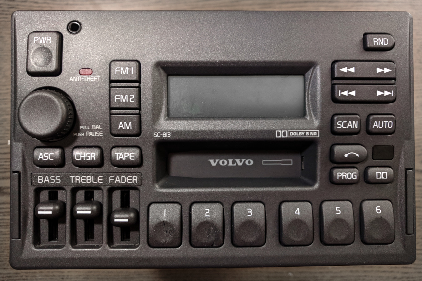
This mod shows the modification process for a Volvo SC-813 headunit found in a 1998 Volvo S70.
Other headunit models may differ internally from the SC-813 so this example may not translate one-for-one between models.
This mod allow you to use any device with an audio output with your OEM Volvo sound system.
This modification is virtually free and provides lossless sound quality as it bypasses the tape deck audio circuit all together.
I was blown away by the audio quality my Volvo S70 was able to produce after this mod.
You also get to keep the factory look which was important to me since my 1998 S70 only had 70k miles and is in mint condition.
Requirements for this modification
- Soldering iron
- Phillips/Plus screwdriver
- Audio cable of your choice
- Functional tape deck
- Dummy cassette
Optional recommended tools
- Lab bench power supply
- Solder wick and/or solder sucker
- Wire stripper
- Flush cutter
- Speakers for testing
Disassembly
In order to preform this modification you will first need to extract the head unit from your car if you have not done so already. In P80 Volvos this is very easy, there are 2 spring loaded clips on either side of the headunit that can be pressed in to reveal handles. Pull the handles to remove the unit and disconnect any cables plugged into the back. Be careful not to scratch your dash trim or shift knob. Once you have the headunit out of the car, take out all of the phillips/plus screws on the top, bottom, and back of the unit. This will allow you to pull the panels off and expose the circuit boards inside. It is not necessary to take off the sides. The back cast aluminium heatsink should separate from the amplifier board. Once separated, gently remove the amplifier board from the headunit. It slides straight up and out from 2 male pin headers on the main PCB.
Modification
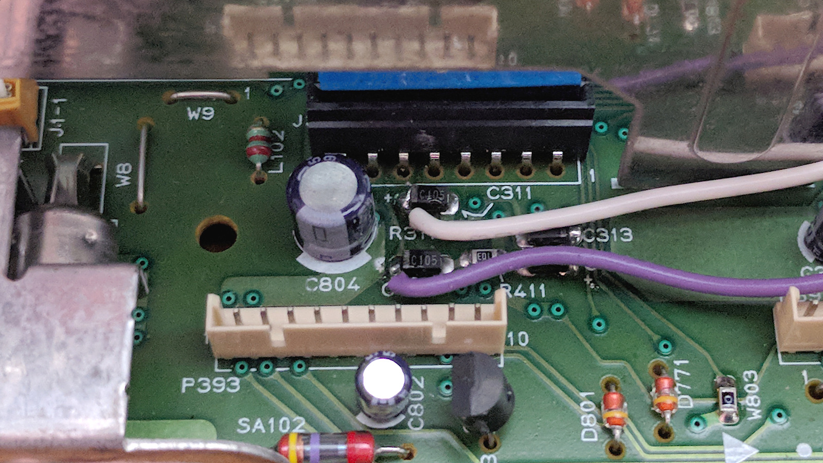
This modification is simple and only really has 2 steps, one of which is not absolutely necessary. Start by soldering the left and right channel wires from the audio cable of your choice to the capacitors as shown in the photo below. Soldering the input before these filtering capacitors and resistors ensures that the audio input will be the correct level and not to "hot" for the fader IC. Injecting the audio here also bypasses the tape deck circuitry to eliminate noise and distortion. Ignore the black wire, this is a ground wire that I ended up moving to the bottom side of the board, see the next step for ground location.
White wire = Left channel
Purple wire = Right channel

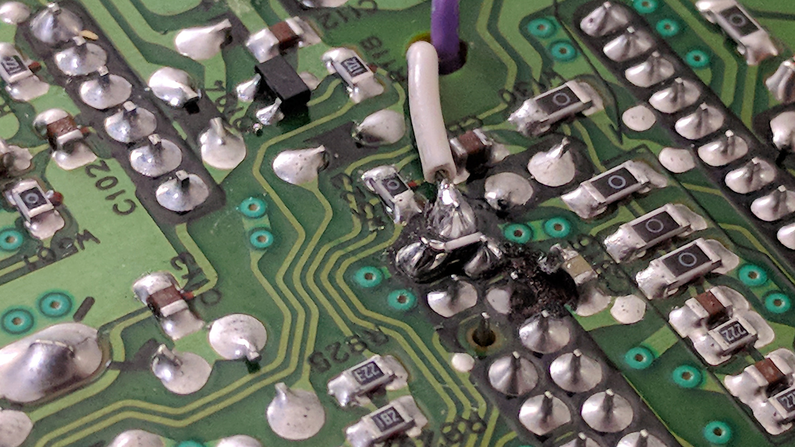
Connect the ground wire where the white wire is connected on the bottom of the PCB. I have a 100 OHM resistor inline to help eliminate ground noise. Try direct ground first and add a resistor between 50-100 OHMs if you have noise. Adding a ground loop isolation transformer can also eliminate ground noise when charging your device. These can be found at many audio shops or online retailers such as Amazon or eBay. You can see a SMD resistor on its side in the photo connecting 2 pins. These are the left and right channels, the resistor is 10K OHM and its purpose is for line level detection. This may not be necessary, my phone detected the aux jack as headphones making the signal to "hot" unless I kept volume low. Adding the resistor allowed my phone to detect the aux jack as a line level input and not try to power the line as headphones. Please excuse the burnt flux residue, I re-soldered this a few times before I found a configuration that worked to my liking.

From here I decided to add a 3.5mm jack on the front panel of the headunit so that it can be unplugged for a cleaner look when not in use. You could also route a cable into the center armrest which already has a pass-through door for accessories like this. In hindsight I would have placed the connector on the other side, or at least further away from the power and volume knob. The cable can get in the way sometimes when trying to change the volume with out looking. I also re-wired my cable from what is shown in the previous photos. I added a shield because my input was picking up noise from the switching components inside the headunit. If you are picking up noise, make sure the internal cable is well shielded and you have a shielded 3.5mm cable going to your device. I still had interference and noise when using my cellphone with a cheap unshielded 3.5mm audio cable. Switching cables solved this. I had trouble with certain devices not detecting the aux input. If this happens to you, power off the headunit and then plug in your device while the headunit is off. Once your device detects the connection, then power on the headunit.

Blank Media
In order to allow the head unit to stay powered on and accept the auxiliary audio input, a silent or blank cassette must be used. I used a cheap cassette to 3.5mm adapter which I removed the cable from and lubricated the gears to eliminate gear noise. You may also be able to use a blank infinite loop tape, I am not sure if the tape head would pick up noise from the blank tape however.
Testing
I recommend testing the unit while it is still disassembled on your bench before installing it in your car. I used my DC power supply and a set of speakers which I connected to back of the unit with small test leads. The pinout for the power and speaker connections are printed directly on the amplifier board on the opposite side of the connectors. Ensure that both right and left audio channels are present and that they are not reversed before assembling the unit. If there is noise, the signal is weak, or you are having other issues, double check that you have soldered the connections to the right pins and test again. You should not need to remove the cassette amplifier from the circuit, if you still have noise you can try using a ground loop isolation transformer.
Alternatives
If this mod is not for you, or you are unable to get it to work, there are other options. The fader IC inside the headunit uses I2C commands in order to switch inputs. You could use a microcontroller and program it to send the I2C commands to the fader IC allowing it to switch inputs to the CD changer. You could then inject the signal into the CD changer input instead of piggy-backing off of the tape deck. This is a better solution but also costs money and time. There are commercial products that do exactly this, most notably the BlitzSafe VOL/AUX DMX V.1. This is a nice pre-made solution that plugs into the back of the headunit via the CD changer port. For someone that does not want to spent the time or rip apart the original headunit, this is a great way to add an auxiliary input. I have not tried one in person so I can not say how the sound quality is, but other people seem to be happy with theirs. You could also just replace the headunit entirely, but this defeats the purpose of this mod, to keep the factory look.
Resources
The schematic for the TEA6320 fader IC used inside of this headunit helped me a lot when tracing down the left and right channels for the tape deck input. Below are images of the fader IC block diagram and pinout in case it is of any help. A link to the schematic for this IC hosted by DigiKey can also be found here:
Sound Fader Control Circuit TEA6320

